Centrala Termica Ariston Microtec 23 Mffi Manual

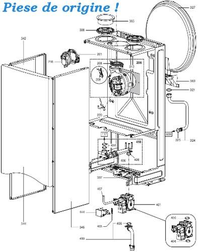
• Servicing Instructions Type C Boilers G.C.N: 47-116-14 47-116-15 LEAVE THESE INSTRUCTIONS WITH THE END-USER Country of destination: GB. • TABLE OF CONTENTS SERVICING INSTRUCTIONS EPLACEMENT OF ARTS ENERAL CCESS - Removing the front panel - Removing the sealed chamber frontal cover - Removing the side panels CCESS TO THE OMBUSTION HAMBER - Removing the combustion cover - Removing the burner and jets - Removing the electrodes - Removing the main heat exchanger - Removing the air pressure switch. The control panel moves downward and when pulled forward, SERVICING INSTRUCTIONS rotates on two lateral hinges; the panel stays in a semi- horizontal position, which allows access to the inner parts of To ensure efficient safe operation, it is recommended that the the boiler (F. • Removing the sealed chamber frontal cover Removing the side panels 1. Remove the screws “C” (F.
Download free Centrala Termica Ariston Microtec 23 Mffi. Mount install recent search washing dryer machine aml lave linge al tfr hotte hes wse shop argd argf. Ariston microGENUS 23 MFFI Pdf User Manuals. View online or download Ariston microGENUS 23 MFFI User Manual.
Remove the four screws “D” for each side panel (F.1.8); 2. Lift the sealed chamber frontal cover from the locating pins 2. • CCESS TO THE OMBUSTION HAMBER Removing the combustion cover 1.
Remove the screws “E” (F. Lift off the combustion cover.
1.12 78 eps Removing the electrodes Before carrying out this procedure, unscrew and slide the burner forward (see previous section). Remove screw “H” (F. 1.15); Removing the main heat exchanger 4. Gently slide the electrode downward (F. Drain the boiler of water; 2. Release the overheat thermostat sensor “I” (F.
Release the two connection nuts “J” connecting the exchanger to the flow and return pipes (F. • Removing the air pressure switch Removing the fan 1. Disconnect the electrical connections “K” and silicon pipes 1. Disconnect electrical connections “N” and silicon pipes “L” from their connection points (F. 1.20); “O” (F.1.23); 2. Remove screws “M” on the top of the sealed chamber 2. • ERVICING AND EMOVAL OF THE ALVE Setting the minimum and the maximum power of the boiler Setting the gas pressures 1.
Check that the supply pressure to the gas valve is a minimum of 20 mbar for natural gas. Lil boosie and webbie gangsta musik zip. To do this, remove the screw “A”. Fit the pipe of the pressure gauge to the pressure connection of the gas valve “B”. • Regulating the heating power for natural gas (G20) model 23 model 27 CG007A Regulating the heating power for butane gas (G30) model 23 model 27 CG008A Regulating the heating power for propane gas (G31) model 23 model 27 CG009A “A” ABLE 2.01 Kg/h 2.00 Kg/h.